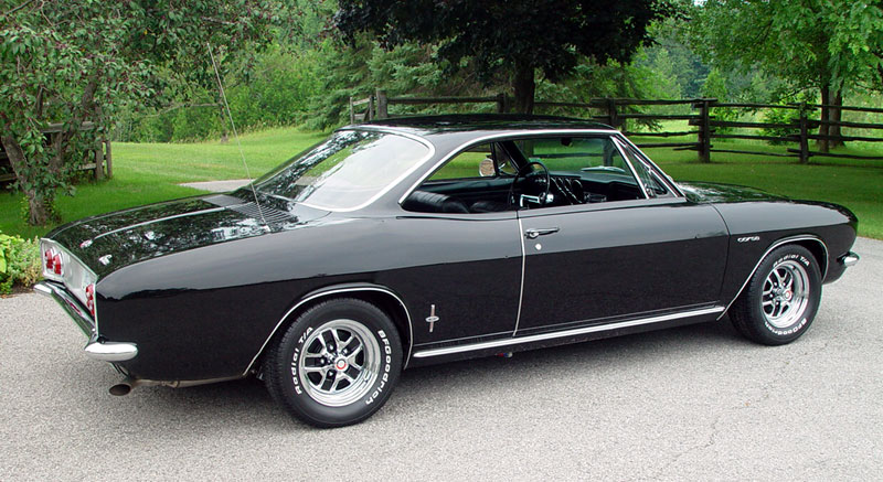
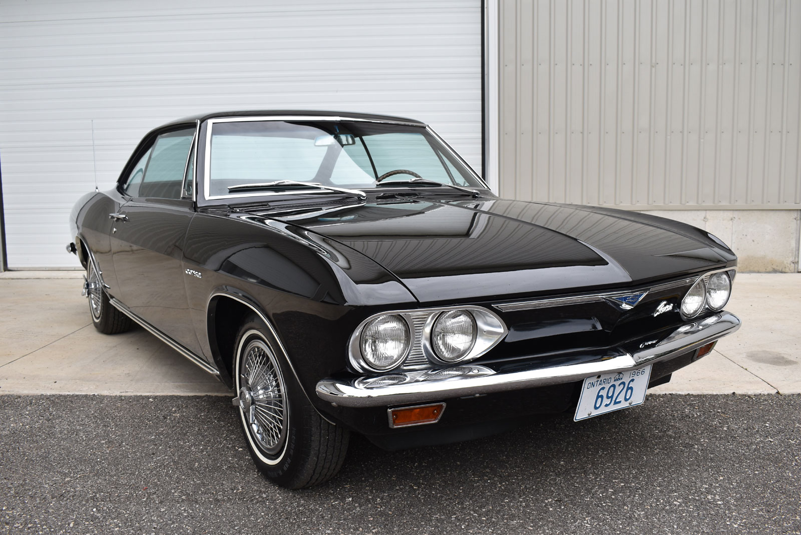
1966 Corvair Corsa - It's Alive!
![]()
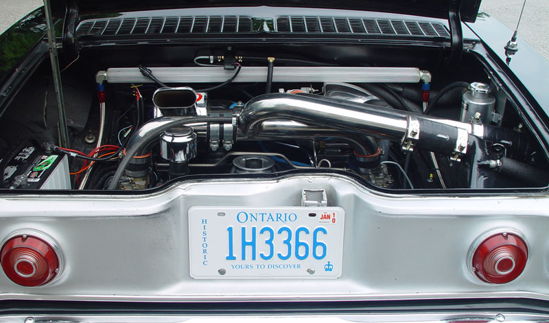
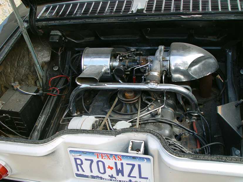
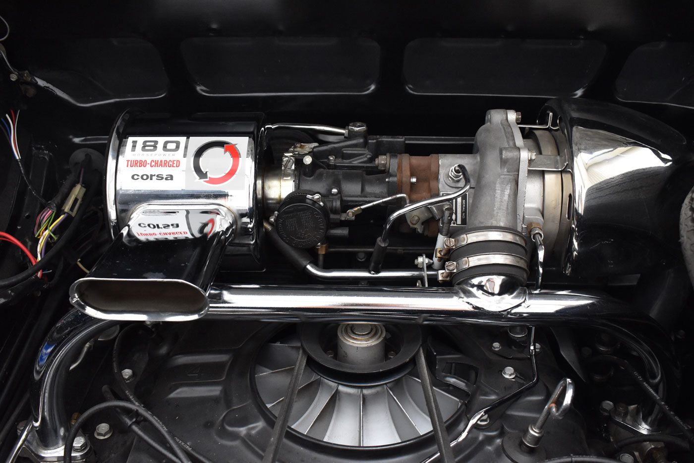
After almost 5 years of rebuilding and modifying the air cooled flat six boxer style engine it is ready to fire.
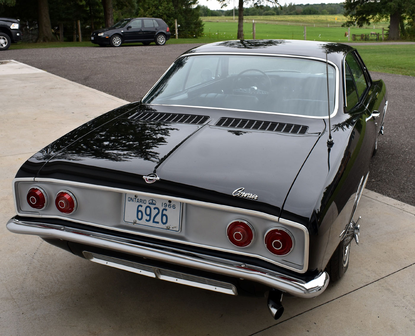
What's that strange noise coming from the back of the car :)
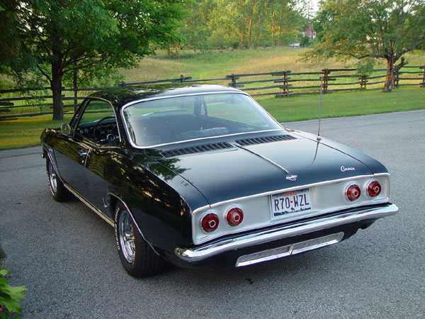
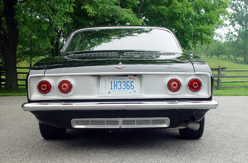
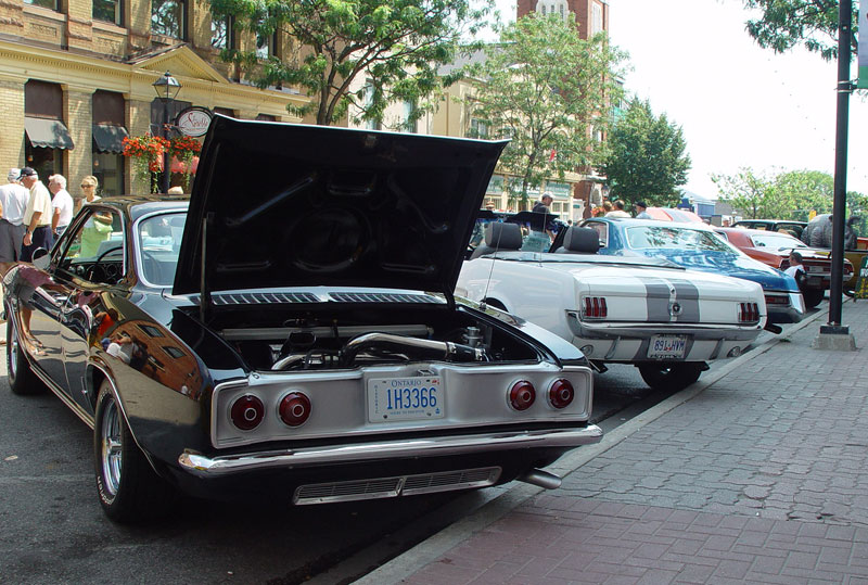
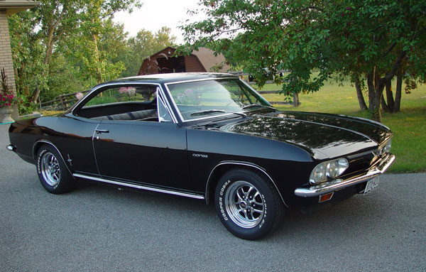
FINALLY - the car moves under it's own power for the first time in 26 years. Paint and body is still factory original for now.
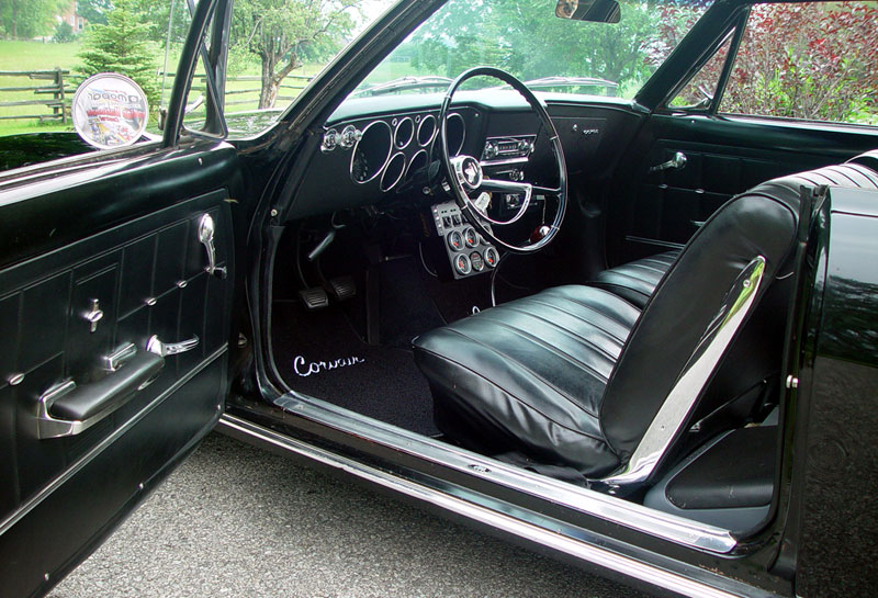
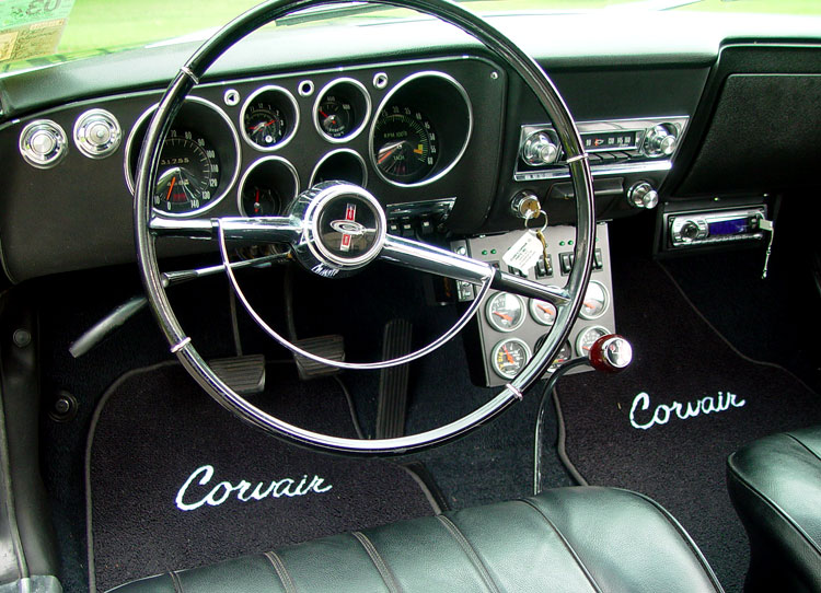
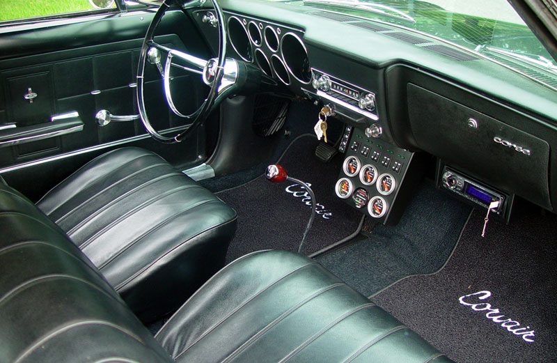
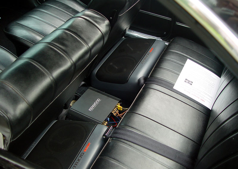
Interior is mainly original, stereo in back seat is temporary
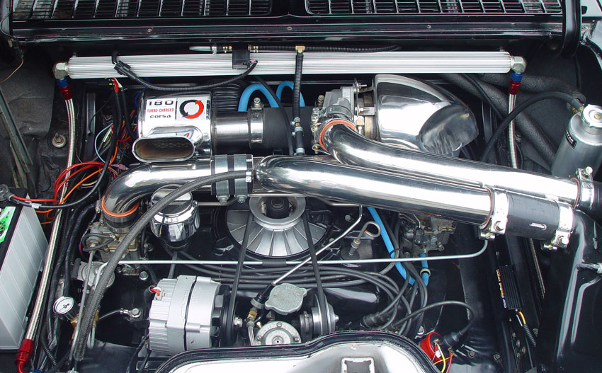
The motor is ......uh......somewhat modified!
Before After
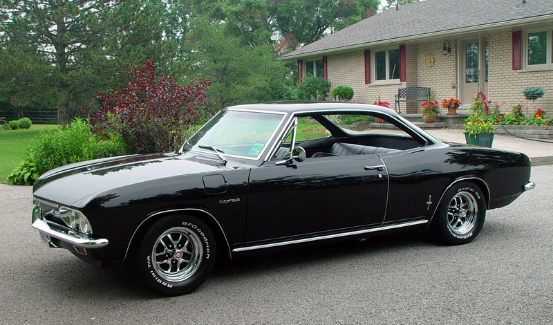
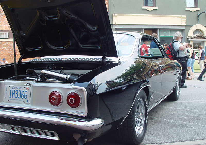
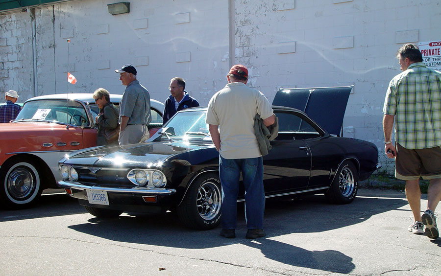
At it's first car show in Orillia ON
![]()
For the full story on this car click here Corvair Page
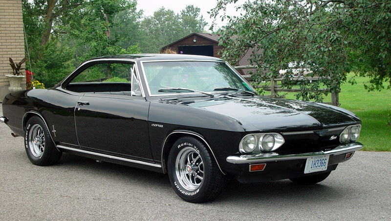
Kim Stankiewicz, a Corvair enthusiast, purchased this car from me and did a full concours restoration on it, scoring 97 out of 100 when judged at the Corvair national convention. It's now totally stock again.
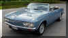
In turn, 10 years later Kim sold me this 65 Corvair Corsa convertible from California, which he has modified in much the same manor as my 66 when he bought it from me.
or click here to return to my Home Page